Vanneck Hand Camera
W. Watson & Sons
| Name: | Vanneck |
| Type: | Single Lens Reflex / Hand & Stand |
| Manufacturer: | W. Watson & Sons |
| Country of Origin: | United Kingdom |
| Construction: | Wooden bodied, leather covered box with integral reflex mirror assembly that also forms part of the shutter. Folding focusing hood allowing scene to be viewed through taking lens. |
| Production Period: | c1890 - c1908 |
| Plate / Film Size: | ¼ plate |
| Lens: | Goerz Patent Double Anastigmat with iris diaphragm 5IN f/7.7, stamped Ross, London, serial number 3983 |
| Shutter: | Time & instantaneous according to advert |
| Movements: | None |
| Dimensions (w x h x l): | 12 x 15.5 x 22 cm (approximate) |
| Date of this Example: | c1902 |
| Serial Number: | Serial number 122236 stamped into the base of the camera on the tripod support block |
| Availability: |
|
| Inventory Number: | 674 |
![[ ]](../../images/unchecked.png)
![[x]](../../images/checked.png)
")
Description
The Vanneck was advertised as a Hand camera by Watsons, but might also be categorised as a Detective camera or Reflex camera. According to McKeown [1] it is the first reflex camera to have an instant return mirror. The maker's name is shown on a rectangular label on the inside of the lid covering the changing bag.
Like the Talbot & Eamer Miral, the Vanneck allows the user to view the scene through a reflex viewer that uses the taking lens, and allows the image to be focused on a ground glass screen built into the top of the camera and viewed through a hood. The mirror assembly forms is attached to the top surface of the flap shutter, so the mirror flips up automatically during the exposure.
This example also has a traditional reflecting finder built into the body that could be used for landscape format pictures. According to the Royal Photographic Society catalogue entry for the year, this "improvement" was first shown in 1893.
The plateholders (12) are held in a reservoir at the back of the camera, with a changing bag built into a removable block that fits above the reservoir. A key on the back of the camera lifts the rearmost plateholder upwards into the bag so that it can then be grasped by the user and moved to the front, ready for exposure. A counter is provided in the centre of the back, tripped by the operation of the T-key that lifts the plate.
")
Focusing is achieved by turning a key located on the underside of the camera. The disk below the key has a scale with markings for 5, 10 and 25 yards. Turning the key acts on a simple brass rack and pinion within the camera that causes the frame holding the lens assembly to move back and forth inside the camera body.
")
There is an additional lever at the rear of the underside that moves between two fixed screws. When I purchased the camera, this lever had the end loop of a spring attached. Checking against an example owned by another collector, the original spring was several inches long and was attached to the vertical spring lever used to set the shutter (refer to the Notes below). A replacement spring has been fabricated as part of restoration work carried out on the camera, as shown in the photograph. Based on the patent it is clear that the spring provided a means of varying the shutter speed by moving the position of the lever and thereby adjusting the tension of the spring.
The Goerz lens was apparently listed by Ross between 1896 and about 1902, and appears to be original to the camera.
There is a thick wooden block on the underside of the camera that carries a tripod bush. The serial number is stamped into the block. There is a second tripod bush built into the side of the camera for landscape use. At the front edge of the bottom panel is an odd metal plate that is unlikely to be original to the camera, as it shows the Primus trade mark around one of the fixing screw heads, and Patented around the other. The purpose of this bracket is not yet known.
The shutter controls are activated from the bottom panel, with one lever to set the shutter and another to release it. There is a cord that is attached to the flap shutter and exits through the top of the body just in front of the hinged cover for the focusing hood, which can be used to hold the shutter open for any longer exposures. The cord was absent when I received the camera having broken inside and has been replaced as part of a partial restoration of the camera (refer to the Notes below).
Notes
The camera name is not shown on the label. Watsons identify it as "Vanneck" in their 1893 BJPA advert, but some references also identify it as "Van Neck". The latter name relates to the identity of the patentee for the camera design, one L. van Neck (British Patent 3482, March 1890).
Comparing the adverts in the 1899 and 1904 BJPAs, there was a significant design change at some point between those dates. The earlier adverts show a top handle, whereas the later cameras such as this example have lugs on the front and rear faces to which the handle was fixed. The handle itself is missing on this example. None of the four examples of the Vanneck camera that I have seen so far match the pattern shown in the early adverts. The later adverts also describe two qualities, "Best" and "Second". In the Best the woodwork is mahogany, while it is whitewood for the Second, and likewise the covering is stated as being of finest morocco for the Best and sole leather for the Second. The example shown here is of mahogany (confirmed after removal of the base).
The camera is constructed of two main components, the outer casing with a removable base, and an inner casing that holds the shutter assembly, lens panel with rack and pinion and the viewing glass. The photograph below shows the principal components of the camera after disassembly. At this stage of the restoration, the only action taken had been to replace the string used for timed exposures.

One of the major elements of the restoration was to make the mahogany strips that were used to hold the base in place. These were completely absent when I purchased the camera. Thankfully I was able to obtain measurements from a camera held by another collector. Four separate lengths of mahogany strip were required, painted black, and fixed to the inside of the casing once the camera had been fully re-assembled. The bottom edge of the strips protrude beyond the casing to form a base surface, and they were lightly sanded to reveal the mahogany to "age" them to achieve a similar appearance to the original example that was being used as the model. They can be seen in the photo of the underside of the camera shown earlier on this page.
When carrying out repairs to the camera, I had to take it apart and remove the inner casing, which is shown in the photographs below along with information about the operation of the shutter.
 |
|
|
|
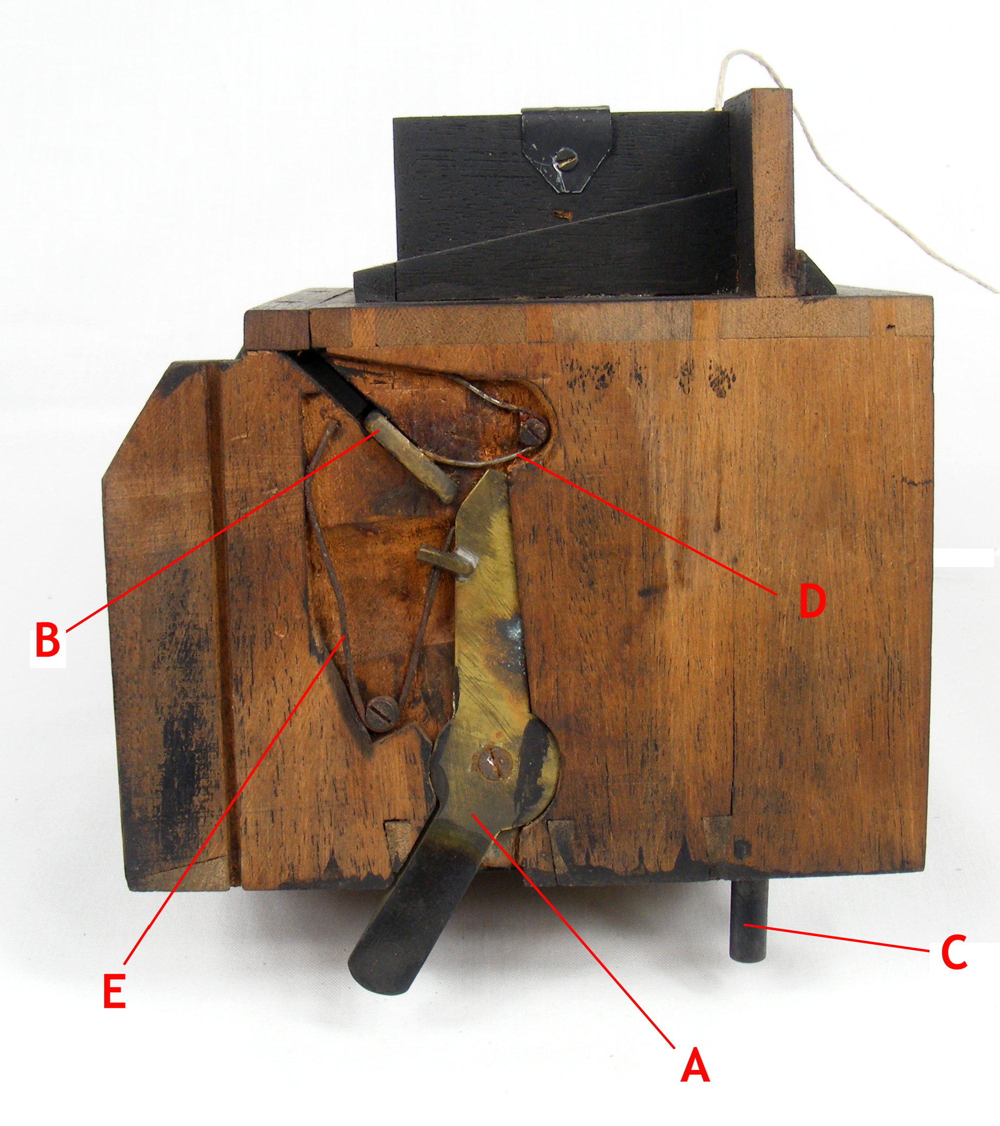
Figure 1: Side view of inner casing showing the main components of shutter mechanism, with annotations that are referred to in the subsequent text. The lens panel is on the right side, and the viewing screen is located on the top face of the casing. A: Vertical spring lever, which has a knife edge at top left B: Flap shutter pivot and arm C: Trigger to release shutter D: Mirror return spring E: Return spring for vertical spring lever This photograph shows the shutter in its normal unset rest state. |
 |
|
|
|
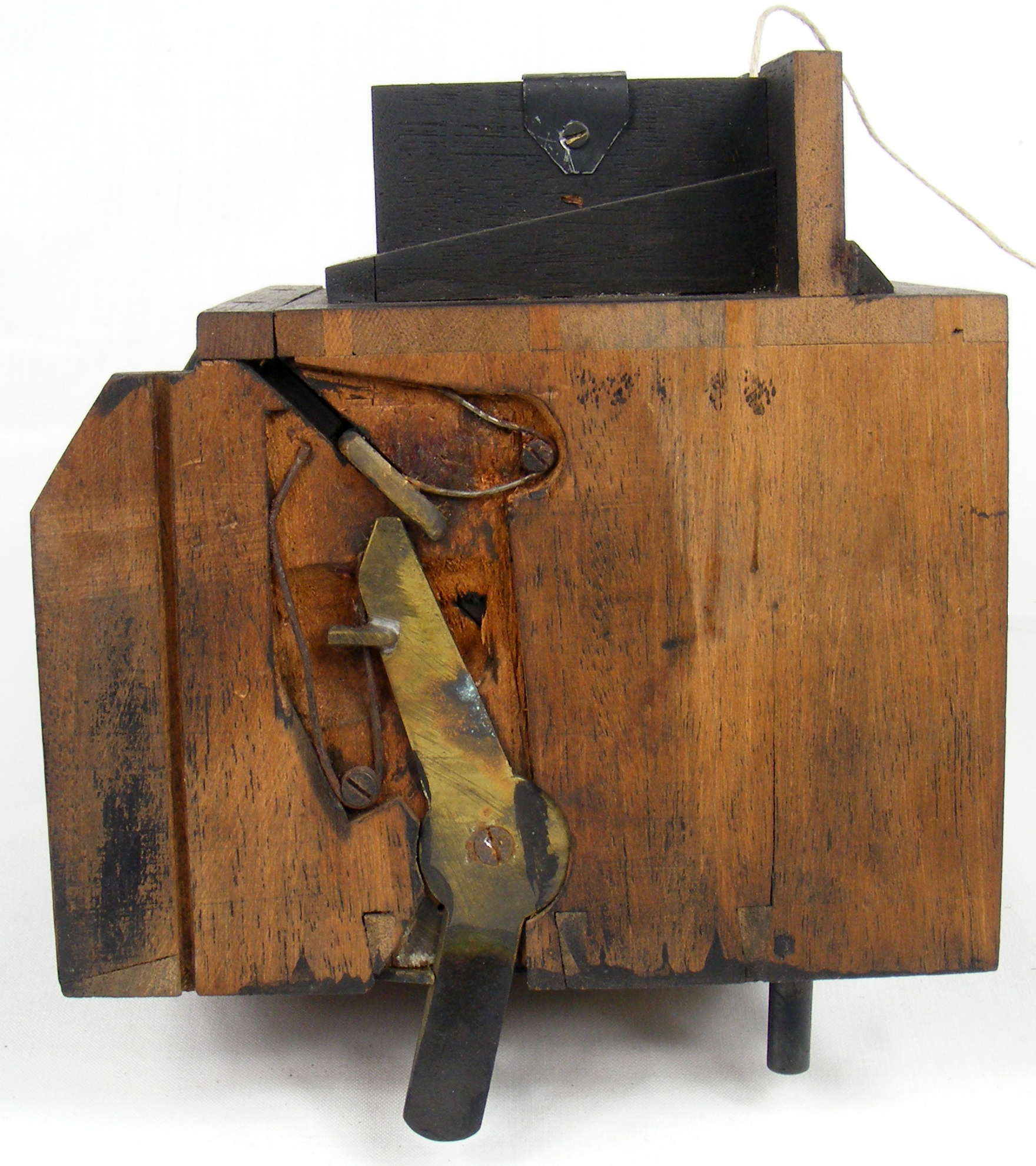
Figure 2: Shutter in its set position. To set the shutter, the vertical spring lever (A) is pushed towards the front of the casing. The knife edge at the top left section of the lever allows it to travel over the pivot arm (B) without causing the flap shutter to move. The lower end of the vertical spring lever is held in position by a catch notch on the trigger pivot arm (refer to Figure 3). |
 |
|
|
|
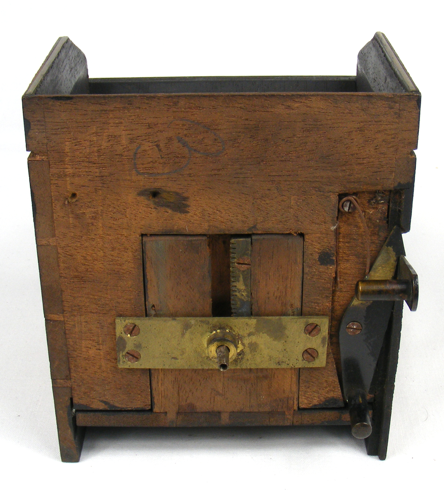
Figure 3: Underside of the shutter casing. This photograph shows the trigger pivot arm on the right, as well as the central rack and pinion that adjusts the position of the lens panel. The vertical spring arm is in the set position, and is held by a notch on the edge of the trigger arm that can be seen at centre right of the photo. When the trigger arm at the bottom right of the photo is pulled towards the side of the casing, the vertical spring arm is released from the notch. |
 |
|
|
|
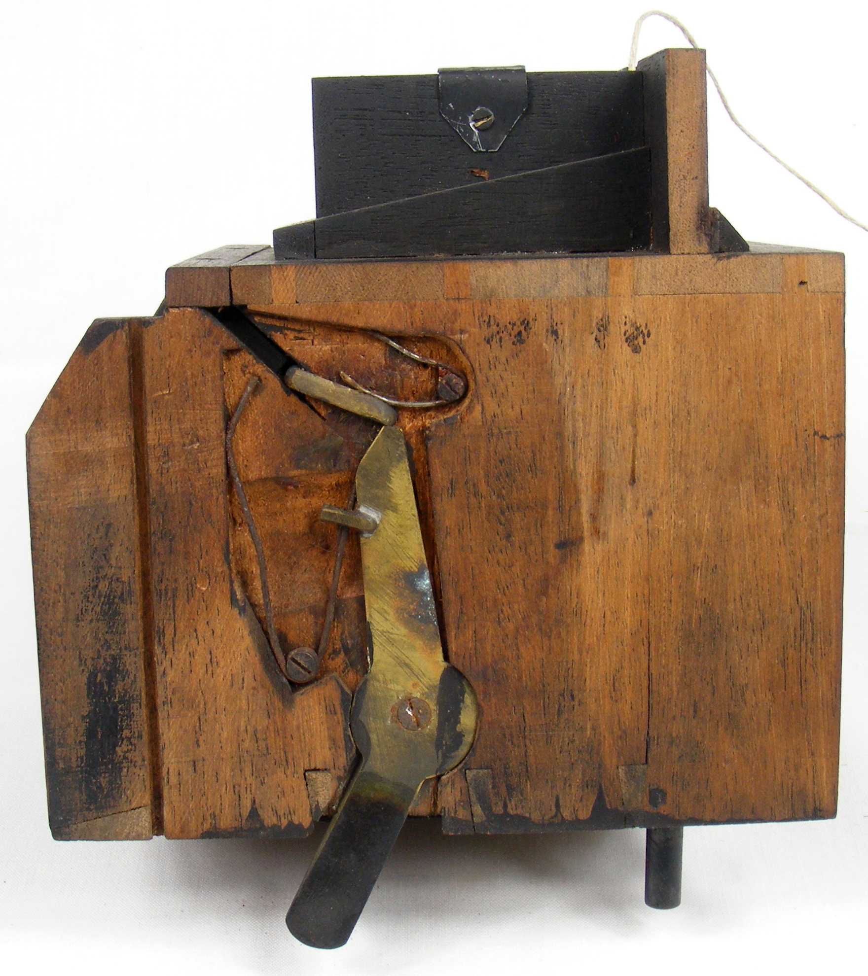
Figure 4: Shutter fired but captured at the point when the flap shutter is open. When the vertical spring arm is released by the user pulling on the trigger arm (C), the thick back edge forces the arm of the flap shutter (D) to move upwards due to the pressure of the return spring (E), thus fully opening the shutter. |
 |
|
|
|
Figure 5: Shutter closes as the arm drops back to rest position. Once the flap shutter is at the top of its travel, the vertical spring arm (A) is able to pass below the top of the pivot arm (B). The vertical spring arm continues its movement back to its rest state, and the flap shutter drops back to its closed position, pushed back down by the return spring (D). The time the shutter is open is further influenced by the tension of an external spring acting on the vertical spring lever (not shown). |
 |
|
|
|
Figure 6: This shows the mirror that is mounted on the flap shutter that is used to focus, as seen through the port on the front of the inner casing. The mirror used to focus the camera is mounted on the upper surface of the flap shutter allowing the image to be viewed on the glass screen above. Note the cord that is fastened to a simple screw ring fixed into the flap shutter, which is used to provide timed exposures. The cord passes through the top of the casing body just in front of the viewing glass, and then passes through another hole in the outer casing. The cord is simply pulled tight by the user to hold the flap shutter open for the desired interval, returning to the closed position when the cord is released by virtue of the return spring (D). |
The photograph below was taken while the camera was disassembled and shows the inside of the rear of the main outer casing. This holds the lever mechanism that is operated by the T-key on the rear of the camera, which acts on the pivot point on the lever at top right corner of the picture.

The bar that is shown in an almost horizontal position is the device that lifts an unexposed plate up into the changing bag. It is shown in the lowered position. The photograph below shows the restored camera, loaded with plates but with the top chamber holding the changing bag removed. The T-key has been turned to the raised position to push the rear plateholder upwards.

When the T-key is used to return the plate lifting lever to its rest position, the other shaped lever (corroded in the picture), which is also pivoted, is forced upwards to engage with and partially rotate the toothed wheel fixed to the rear of the camera body. This is inscribed with numbers to act as a counter, read through a hole in the rear of the camera.
I am engaged in some research into cameras made by W. Watson & Sons in order to try and establish some guidance on likely manufacturing date based upon the serial number. This is in fact quite difficult to do currently as many patterns of Watson cameras were made for very long periods with few significant design changes.
If you have a Watson camera, then I would be grateful if you could provide me with further information about your camera, even if it is not serialised. Please refer to the Watson Research Project page for further information.